
RADIO TUBE TUNER PHILIPS A5X93A/01
 *Radio Tabung ini disebut Radio Tuner karena hanya mengunakan perangkat Tuner/penerima saja tanpa menggunakan penguat Power untuk ke speaker. Apabila menggunakanya Tuner ini perlu membutuhkan penguat audio seperti Amplifier sebagai penguat suara ke speaker. Radio ini diproduksi negara Belanda tahun 1963 dengan label Made in Holland, Radio ini cukup lengkap dengan daya penerima glombang : LW, MW, SW1, SW2, dan FM stereo dari berbagai stasiun pemancar radio dengan daya penerimaan sinyal radionya cukup sensitif dan bagus sehingga semua frequensi masih befungsi dengan baik. Saya menggunakan pasangan Radio Tuner ini menggunakan Preamp dan Power tabung dengan suara sangat jernih dan jelas di semua frequensi. Maka Radio Tuner ini sangat cocok di gabungkan dengan perangkat audio tabung (amplifier) kelas HI-END dengan suara FM stereo cukup bagus mendekati suara CD dengan suara vokal dan musik yang natural dan jernih dengan vokal cukup tebal tidak seperti radio-radio tabung FM stereo pada umumnya. Pada waktu saya coba bandingkan Radio Tuner Tabung ini dengan Radio Tuner Solidstate merk lain seperti Tuner merk AKAI produksi lama yang masih menggunakan varco besi di dalamnya, menurut saya Tuner AKAI paling bagus dibandingkan merk KENWOOD, SONY, AIWA yang pernah saya coba badingkan. Setelah saya mendapatkan Radio Tuner Philips A5X93A dan saya bandingkan ternyata cukup jauh berbeda alhasil Tuner Solidstate dengan suara lebih tipis dan kering tidak seperti Radio Tabung Tuner Philips A5X93A dengan Suara Vokal Warm, Clear dan Open, Maka radio tuner Philips A5X93A ini di pasang label STEREO HIGH FIDELITY Pada layar scala depan oleh pabrikanya. Radio tuner ini waktu saya mendapatkanya cukup orsinil dan dengan kondisi hidup dan normal namun pernah saya upgrade di bagian kathoda by pass memakai componen audio Hi-End jenis blackgate alhasil cukup lebih bagus dari pada hasil semula sebelum saya pasang componen jenis blackgate tersebut dan radio ini menggunakan jenis tabung ECC85, ECH81, EF89, EM84, EABC80, ECC82, EZ80 dan Dimensi : 350 x 140 x 290 mm / 13.8 x 5.5 x 11.4 inch
 **Beruntunglah bagi mereka yang telah mendapakan radio ini karena dirumah tidak perlu memutar CD untuk mendengarkan musik karena radio ini sudah cukup bagus dan hangat di telinga yang pernah saya bandingkan tidak seperti radio tabung FM stereo pada umumnya karena radio ini di buat cukup special oleh pabrikanya di lihat dari rangkaianya yang cukup rumit dan tabung-tabungnya sehingga menghasilkan suara yang real dan komplit di smua lini. Dalam pelestarian sejarah radio ini supaya tida punah Radio Tabung ini telah di simpan di museum radio di negara eropa oleh salah satu kolektor radio tabung silahkan klik disini Demikian sedikit pengalaman yang pernah saya coba Radio Tuner A5X93A ini semoga bermamfaat bagi pecinta Radio Tabung.
DATA SHEET
RADIO TUBE PHILIP A5X93A
RADIO TUBE PHILIP A5X93A
|
| ||||
| Anno: 1963-1965 | Tipo: Radio - o sintonizzatore passato WW2 | ||||
| Valvole | 8: ECC85 ECH81 EF89 EF89 EM84 EABC80 ECC82 EZ80 | ||||
|---|---|---|---|---|---|
| Semiconduttori (transistor contati solo) | 6: AF126 AF126 AF126 OC75 OC75 AC127 |
| Circuit | Supereterodina (in general); Frequenza intermedia 452/10700 kHz IF |
|---|---|
| N. Tues CIRCUITI accordati | 9 CIRCUITI Mod Amp (AM) 11 CIRCUITI Mod Freq. (FM) |
| Gamme d'onda | Onde medie (OM), onde lunghe, 2 corte e onde FM. |
| Tensioni Tues funzionamento | Alimentazione a corrente alternata (CA) / 90, 110, 127, 145, 165, 190, 220, 245 volts |
| Altoparlante | - For headphones or amp. |
| Radiomuseum.org | Model: AM-FM tuner A5X93A/01 |
| Materiali | Vari materiali |
| Formative | Apparecchio by a ripiani scaffale (come i Componibili HiFi). |
| Dimensioni (LxAxP) | 350 x 140 x 290 mm / 13.8 x 5.5 x 11.4 inches |
| Annotazioni | AM-FM Tuner Philips A5X93A/01; AM-IF 460 kHz for version ../19. transistorized stereo decoder. |
Posted modello da Iven Müller . Submit resources "Proponi modified" by inviare Ulteriori dati.
Elenco delle radio e altri apparecchi della Philips, Eindhoven (tubes internationally!), Netherlands
In questo sono link elencati modelli 2509, di cui con 2146 1719 con immagini e schemi.
In questo sono link elencati modelli 2509, di cui con 2146 1719 con immagini e schemi.
Nel forum Discussioni su questo modello Philips, Eindhoven: AM-FM tuner A5X93A/01 Argomenti: 3 | Articoli: 8
Visite: 553 Responded: 0
 philips: A5X93A/01, AM-FM tuner: stereo decoder philips: A5X93A/01, AM-FM tuner: stereo decoder | |
| Dietmar Rudolph 03.Dec.10 | 1 The A5X93A is one of the first stereo-capable tuner. Consequently, his stereo decoder is also an early version of this genre. A description can be found in: "Schanz, GW: Paperback stereo, stereo equipment for the practitioner , Philips Pocket Books, 1966. "
5.1 Switching Decoder
Section 3.2 has already been shown how in principle a point on the receiving end switch with a convenient switch on the transmitter side at the same time can allow switching between left and right channel stereo transmission of signals over a single transmitter to the receiver. Of course no one would come up with the idea of such a switch mechanically execute. The switching frequency is less than 38 kHz! It is so close that the solution electronic character wears.

Looking at the block diagram shown in Figure 5.1, it is seen as the first link that follows the ratio detector, a lowpass filter with cutoff frequency f g = 55 kHz. The low pass filter can therefore pass the entire stereo signal. As is well known for the synchronous switching between two channels, a 38-kHz voltage is required. To the 19-kHz pilot tone from the stereo signal is doubled and then sieved. With the thus obtained two 38-kHz voltage acting in antiphase switches are controlled, where is the full stereo sound. For in-phase operation will be in the 38-kHz rhythm always switched at the right moment and consequently causes a good separation of the two channels.
However, as can be achieved even with completely accurate switching is not an absolute separation of the two channels can be made subject to a so-called crosstalk compensation use. The reasons will be explained shortly. First shown in Fig 5.2 is a stereo pilot tone signal without the presence of only one channel (R = 0).

It is therefore at the transmitter side channel between the L and zero back and forth.The result is very steep voltage edges, would exceed kHz to transmit under 53, but the bandwidth significantly. But since even before the modulation of the transmitter, all frequencies are cut off above 53 kHz, resulting slanted, biased toward the sinusoid flanks. Switches the decoder according to Figure 5.2 from the left channel to the right (R = 0), so there are still remnants of the left channel voltage present (hatched).

In Figure 5.3a again the stereo signal is shown with its sloping flanks. In the left channel of the decoder due to in-phase switching in the 38-kHz pulse rhythm resulting voltages are shown in Figure 5.3b. Behind-the de-emphasis filter section which follows the voltage is indicated by dashed lines mean, ie, in the low-frequency signal. Figure 5.3c shows in a clear manner in the case assumed in the correct phase change in the right channel (R = 0) resulting voltage residues. It is seen that despite the transmitter end in the right channel completely missing in the modulation decoder creates a tension that of those in the left channel is dependent. It is formed by the sloping flanks namely in the left channel! Consequently, there can be a cross-talk the talk.
Would no crosstalk compensation would be available, set at the de-emphasis filter section-also an NF-useful signal, in accordance with the dashed curve in Fig 5.3c. Thus would arise in the right channel unmodulated signal with the same frequency as the modulated left channel (see Figure 5.3d). It therefore makes sense to add within the decoder signal components corresponding to the modulated channel phase reversal in the opposite polarity of the unmodulated channel. This is indicated in Figure 5.3e. This is the area of the curves practically razed by appropriate settings of the compensation voltages in both positive and negative, so there is minimal crosstalk. Due to screening of the 38-kHz voltage must be in the best case, the resulting average coincide with the zero line. However, is clear that by the inevitable asymmetries existing enclosed by the curves always leaving a small residual cross-talk, of which the representation in Figure 5.3f gives an impression. It must not be overlooked that this type of compensation not based on the mutual annihilation of two exactly opposite phase coexisting tensions. In such a case, the mean would of course be zero, which would correspond to a perfect compensation. Rather, the cross-talk compensated only after the averaging time-of-phase-shifted voltages.
Figure 5.4 shows the practical implementation of a switch decoder [43: NN: AM/FM-AC Super Capella Reverbo B7X43A; German Philips GmbH, Service Department, Hamburg, 1963].

The input of the decoder is connected to the ratio detector. The coil of the S 101 and the capacitor C 201 is formed resonant circuit tuned to the frequency of the pilot tone (19 kHz). The thus filtered pilot frequency is the base of transistor TS 201 fed. The collector circuit of transistor located in the transformer is likewise matched kHz to 19. The amplified pilot signal appears at the coil from the S 105 and S 106 connected secondary winding formed, whose center tap to ground. By means of the two diodes Gr 201 and Gr202 existing full-wave rectifier circuit is doubled, the pilot frequency kHz to 38. This frequency is at the load resistor R 205 and through transistor TS 202 reinforced. She is in the collector circuit of transistor TS 202 through the coil, S 107 and the capacitor C 209formed sieved filter and from the secondary winding S 108 / S 109 the Ringdemodulatorwith the diodes Gr 203 , Gr 204 , Gr 205 and Gr 206 fed. The stereo signal is connected through a coil of the S 103 and the capacitor C 205 formed trap for the SCA signal (vgl.Abschnitt3.2. 1) at the center tap of the coils of the S 108 and S 109 existing secondary winding. Ringdemodulator in the regenerated subcarrier signal is demodulated. It forms together with the sum signal at point Y (connection point R 210 / Size 203 / R 215 ) the left and the point Z (connection point R 211 / Size 205 / R 214 ) the right stereo information. This information is about the Deemphasisglieder R 223 / C 213and R 222 / C 214 sent to the two low-frequency amplifier channels.
The final stage of the transistor TS 203 is used for crosstalk compensation. Is switched to an assumed straight time, for example on the right channel, then flows through the resistors of the R 213 and R 214 voltage divider formed a fraction of the right signal to the base of transistor TS 203 . Amplified this signal out of phase fraction appears at the collector and the resistor R 221 to the left channel added. This measure corresponds to the context of Fig 5.3e given explanation. With the help of the adjustable resistor R 213 , the crosstalk compensation be dosed so that a minimum result of crosstalk. Is switched in the following time on the left channel, passes to the of the resistors R 213 and R 215voltage divider formed a fraction of the left signal to the base of transistor TS 203 . This will in turn opposite phase having been strengthened through the resistor R 220 to theright channel added. The bound in both cases, the channel added their own share affects only insignificant effect on the output amplitude. Since the power supply shall be made from the operating voltage of the decoder tipped tube receiver, the negative terminal of the circuit is grounded.
A slightly different circuit drawn of the stereo decoder is found in. "Diefenbach, WW: Practice of stereophonic broadcasting , radio-photo-cinema technology, 1965. " Here also the connection for a stereo indicator is shown, in this case an EM87. 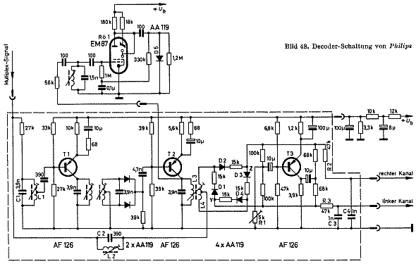 In early solutions (other companies), it was common for example with the aid of a relay the signal between mono and stereo switch be reclassified to adapt that for the single decoder is bypassed and therefore not have the disadvantages can occur. From the diagram of the A5X93A is to recognize that there is no provision for such a change. (The stereo decoder is shown here only as "Box.") I just like the developers thinking?  MfG DR |
Visite: 782 Responded: 0
philips: A5X93A/01, AM-FM tuner: AM & LW Balance | |
| Dietmar Rudolph 15.Nov.10 | 1 The input section for MW and LW has a belt filter input. The special feature is the coupling of the two circles for both MW and LW for. It is in both cases the base point of a capacitive coupling. In addition, MW is one mittenangezapfte coil ( S 17, S 18) involved, while LW is a purely capacitive coupling foot, but also with two trimmers C 15 & C 17, the coupling can be affected. The filter band-coupling via a coil with a center tap was used especially for straight stereo receiver. The AM input of a tuner, it represents a special dar. 
The tuner is in this measurement is not turned on!
   The sudden change in resonant frequency was found to be defective at the core of S out 15th Here, the ferrite core was separated from the brass screw and had slid down inside the coil. There is a problem, as do the filtering band from Philips (Micro-band filter) occurs. Luckily, you have to drill here, no extra hole to get to the ferrite core, as it is necessary for the bandpass filters. The individual counties have one from bottom to top continuous Plastikhalm, which can move around the nucleus. The brass screw can turn down towards the top, while the ferrite core and its plastic sleeve can be pushed easily with a thin insulating down. Brass screw, use plastic sleeve and ferrite were treated with 2 component glue back together, and one day dried. To reintroduce the repaired tuning core into the coil, it was necessary to Plastikhalm widen slightly above the coil, but this had no effect on the function of Schraubmöglichkeit. The transmission curves for MW are now reached for several frequencies reproduced here.     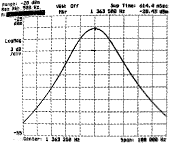  Measurements were made of the transmission curves for LW.     MfG DR |
| Dietmar Rudolph 22.Nov.10 | 2 In addition to the adjustment of the input bandpass filter for LW / MW, the transmission curves of AM were checked IF filter. Fortunately there was no problem with a loose core. The measured center frequency of the IF filter is 461KHz. When measuring the signal generator was directly (without a dummy antenna) to the stator of Cconnected 18th The first IF bandpass filter is decoupled by the heptode ECH81. The button was pressed for MW, it is a connection to the grid 1 ECH81. The 10:1 probe tip for measurement receiver was at the junction between the capacitor C 61 and the trimmer C connected 73, which lies at the foot of the last IF circuit. Although the results in less (but sufficient amount) signal, but a good decoupling and so little reaction to the last band filter.   According to an adjustment in the "broad" was omitted, since the slight tilt in virtually no noticeable tone. Only the NF-harmonic distortion could be reduced somewhat if the IF curve would be exactly symmetrical. This would have an impact but only with "local channels", because the reception of distant stations, the propagation-related disorders predominate. MfG DR |
Visite: 1000 Responded: 0
philips: A5X93A/01, AM-FM tuner: NF-jack | |
| Dietmar Rudolph 09.Nov.10 | 1 The tuner has an unusual Philips A5X93A jack as audio output. 
In the diagram (excerpt: impedance converter with ECC83) the 5 ports that are used here can be seen, good.

The mass is taken out three times.
Philips has obviously uses a special connector, presumably at a connecting cable that was used between the tuner and amplifier.
|
| Hans M. Knoll 09.Nov.10 | 2
Hello Mr. Rudolph.
This plug-in was a proposal to IEC? for a recording-playback for consumer audio connection.
Advantage, separate ground wires A / W.
The Philips has just used the rest of the industry has made the Tuchel Studio connection to DIN connection (eg, 5-pin) DIN 45 321 or IEC 601030-9.
In stereo. Amplifier AG 9016 is included the socket.
Further details are not currently familiar to me.
Two adapters on flat than round DIN IEC system.
Gruss Knoll
|
| Dietmar Rudolph 10.Nov.10 | 3 My special thanks go to Hans Knoll, who - as always - could give a precise answer. If for some reason I should not raise a matching plug, I will be cut as a (reversible) a stopgap RCA extension cable and solder the part with the couplings to the IEC socket and hang out behind the two couplings. Thus it will be possible to operate the device interesting. Dear Mr. Knoll, I always marvel at your amazing detail in addition to your extensive knowledge of general knowledge.What would be the radio museum without your many contributions, even if they become rarer lately, which is very unfortunate. I am not speaking only for myself, if I give the hopes that we will soon be able to read something more of your interesting contributions in RM.org. Kind regards Dietmar Rudolph |
| Dietmar Rudolph 15.Nov.10 | 4 There have been reported as three members of the RM.org and offered this plug or adapter. I am overwhelmed by the helpfulness. All thank you very much! The "fastest" of these offers of help came from Mr Penker, which I hereby wish to express my special thanks. He sent me a plug and a built-in socket.  Dietmar Rudolph |
| Dietmar Rudolph 07.Dec.10 | 5 In "Schanz, GW: Paperback stereo ., Philips, 1966, pp. 28, 29 'are presented the (then) common connector for NF-lines.  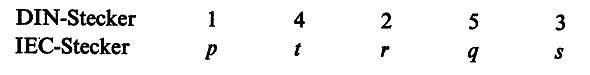 |
Philips, Eindhoven: AM-FM tuner A5X93A/01
Fine delle Discussioni nel forum su questo modello
Fine delle Discussioni nel forum su questo modello
- Info su Radiomuseum.org
- |
- Contacts
- |
- Pubblicità
- |
- Protezione dei dati
- |
- Copyright
- |
- Banner
- |
- Invia ad un amico